
MUTOA Zone Cabling: 3 Planning Decisions That Prevent Certification Failures
2026/04/09 HCI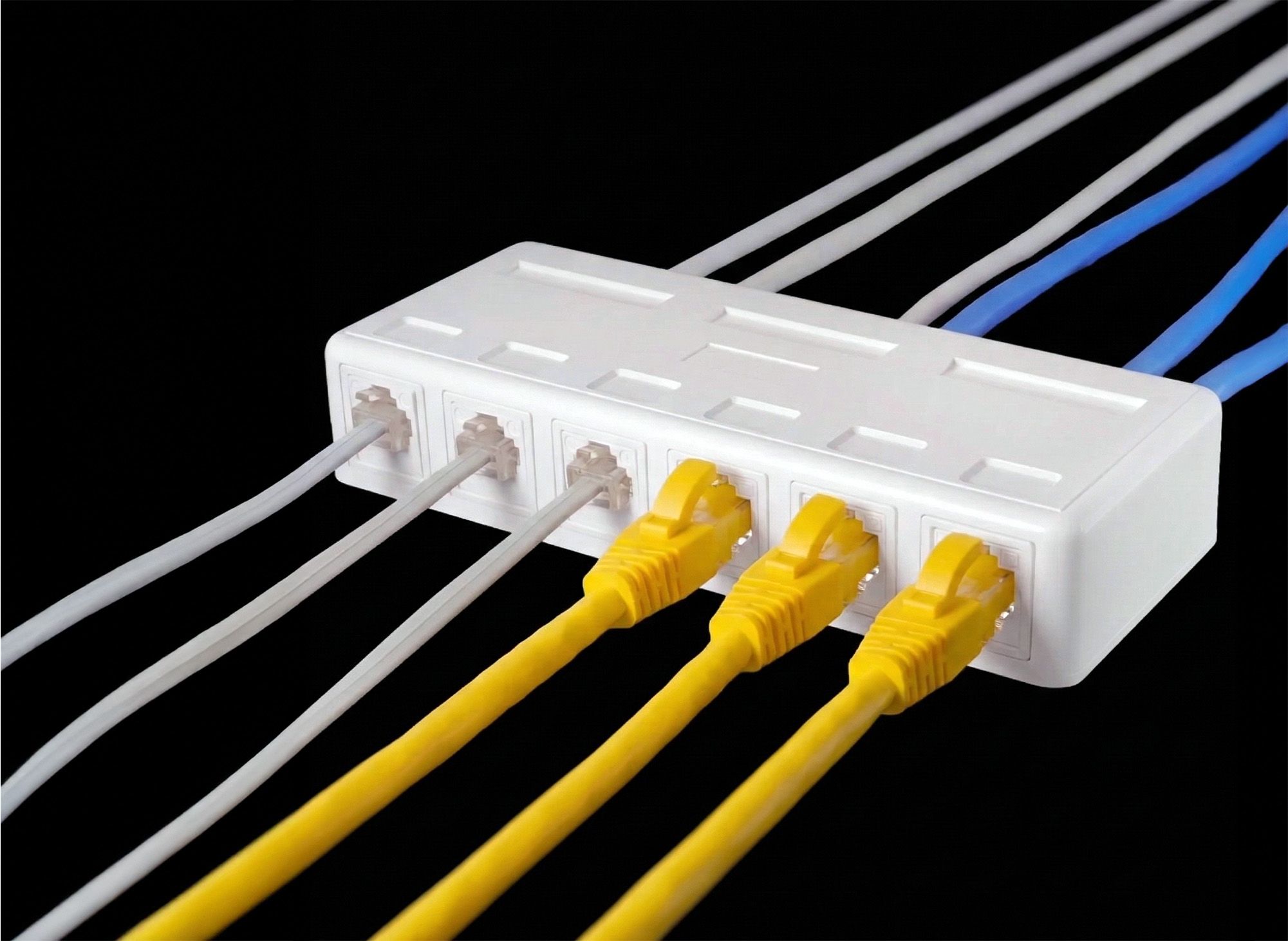
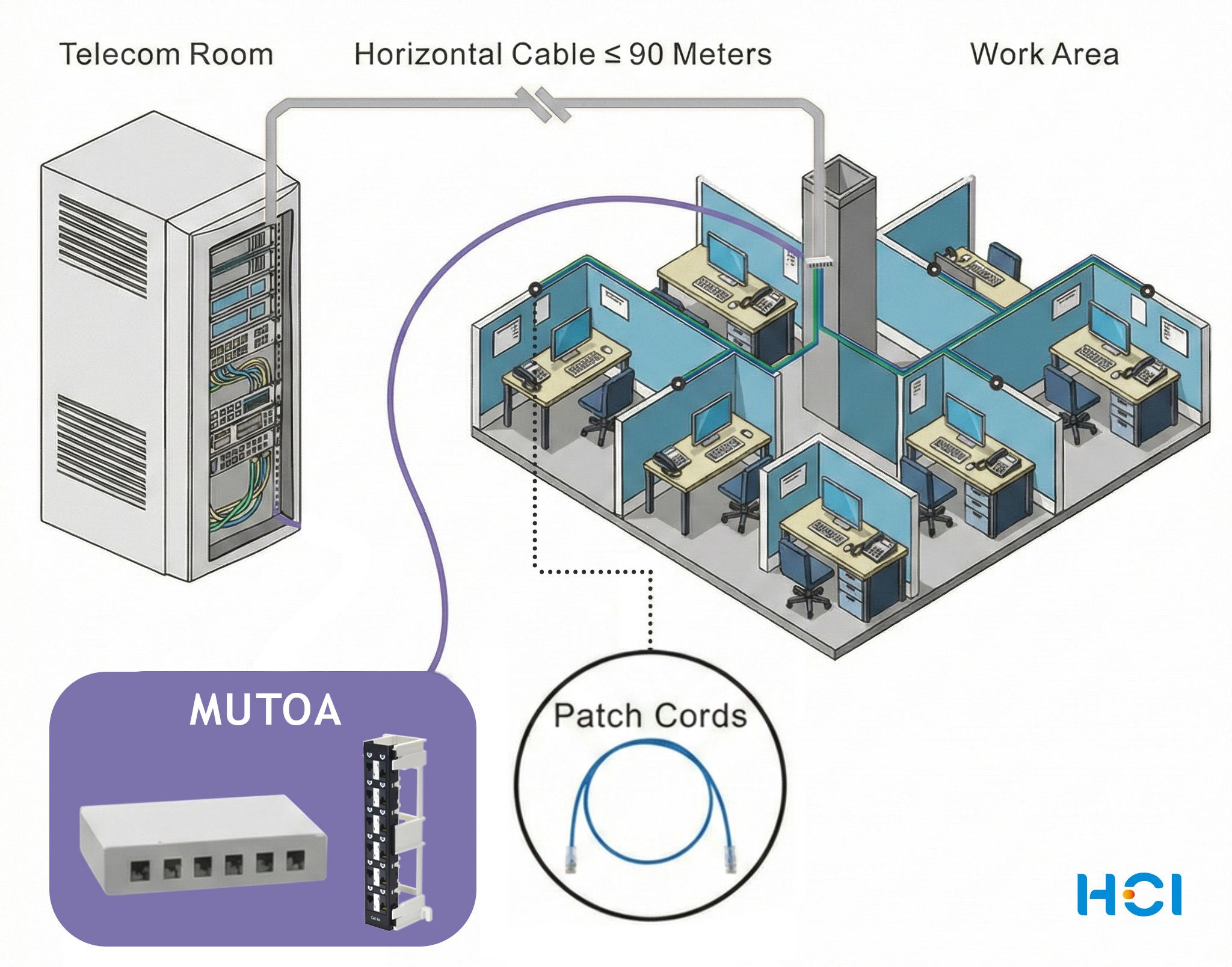
MUTOA Zone Cabling
Open office layouts are designed to change. Desks move, teams expand, and devices are replaced or added over time. While Wi-Fi supports mobile users, many workplace systems still rely on secured stable wired connectivity for desktop workstations, VoIP phones, PoE devices, security systems, and other high-bandwidth applications.
The challenge here is: how to maintain standards-compliant infrastructure while still allowing the workspace to evolve.
This is where MUTOA (Multi-User Telecommunications Outlet Assembly) zone cabling becomes valuable. Instead of running a dedicated horizontal cable to every desk, several horizontal cables terminate at a shared outlet location. Workstations connect to that point using patch cords routed through furniture pathways or floor systems.
When designed correctly, this approach reduces horizontal cabling density and allows moves, adds, and changes to happen in the work area rather than in the telecommunications room. However, whether a MUTOA installation actually delivers that flexibility depends on several decisions made before installation begins.
Three planning factors have the biggest impact: placement, port capacity, and accessibility. These determine patch-cord length, channel performance margin, and how easily the workspace can adapt to future layout changes.
Quick Design Rules for MUTOA Deployments
- One MUTOA may serve up to 12 work areas (per ANSI/TIA-568.1-E)
- Patch cords in MUTOA environments can extend well beyond the traditional 5 m work-area limit, sometimes reaching 15–22 m in open office pathways
- Central placement helps keep patch cords shorter and preserves the channel attenuation budget
- Slim patch cords (26AWG / 28AWG) require derating calculations that may reduce allowable horizontal cable length
With these design rules in mind, let's look more closely at how each planning decision affects real MUTOA installations.
1. Central Positioning Within the Workstation Cluster
The physical placement of a MUTOA determines how efficiently it can serve the surrounding workstations.
In many open office installations, wall-mount patch panels or surface mount boxes are attached to structural columns or pathway exits simply because those locations are convenient during construction. But, placing the MUTOA at the edge of a workstation cluster often forces desks on the opposite side to use significantly longer patch cords.
Standards allow these cords to be longer than traditional work-area cords. In a typical outlet design, work-area cords are limited to about 5 meters. In a MUTOA environment, however, structured cabling guidance allows patch cords to extend much further—up to 22 meters (72 ft) in some deployments—because the cords are routed through controlled furniture pathways rather than loose desk connections.
While this flexibility is useful, it introduces two practical concerns.
First, cable management becomes more difficult within furniture pathways or under raised floors. Studies of patch-cord management in commercial installations have found that more than 90% of patch cords are longer than necessary, which creates clutter and makes troubleshooting more difficult.
Second, longer work-area cords consume more of the available channel performance budget. According to the structured cabling model defined in ANSI/TIA-568.2, a complete channel consists of up to 90 meters of permanent link cabling plus 10 meters of patch cords between the telecommunications room and the work area. When slimmer conductors such as 26AWG or 28AWG patch cords are used, their higher insertion loss can further reduce the allowable horizontal cable length. For example, a 26AWG patch-cord bundle totaling 20 meters can reduce the allowable horizontal cable length from 90 meters to roughly 72 meters once derating factors are applied.
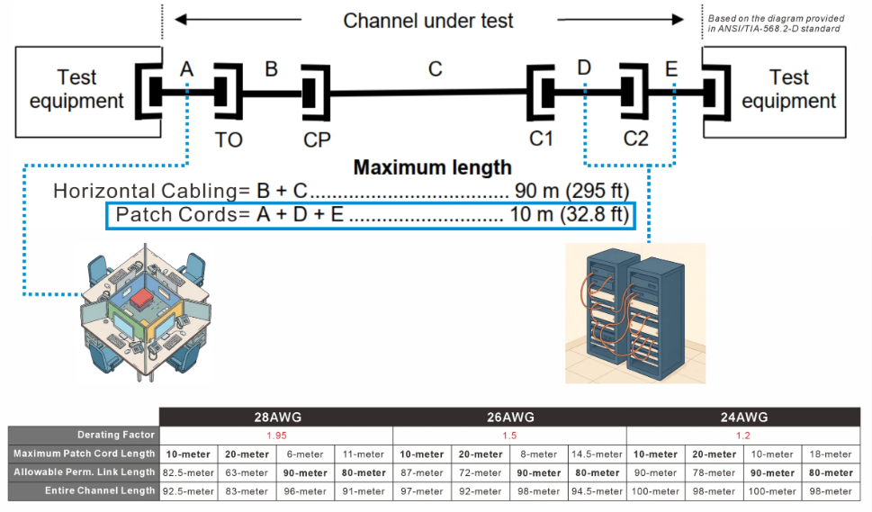
(For the explanation of patch-cord derating calculations, see the reference guide here.)
For this reason, best practice is to position the MUTOA as close as possible to the center of the workstation cluster it serves. Central placement keeps patch-cord lengths shorter and more balanced, improving cable management and preserving channel performance margin.
In most open office deployments, mounting the MUTOA on a structural column or an accessible furniture pathway near the middle of the desk group provides the best long-term flexibility.
In higher-density zones where multiple horizontal cables terminate together, installers often use a wall-mount patch panel on the column to keep cable routing organized and easier to document.
2. Matching Port Count to the Cluster Size
ANSI/TIA-568.1-E specifies that a single MUTOA may support up to 12 work areas. Within that limit, the correct port capacity depends on the size of the workstation cluster and how frequently the layout is expected to change.
For example, a six-desk cluster may only require a small enclosure, while a ten-desk group may justify a 12-port solution to allow for modest growth or additional devices.
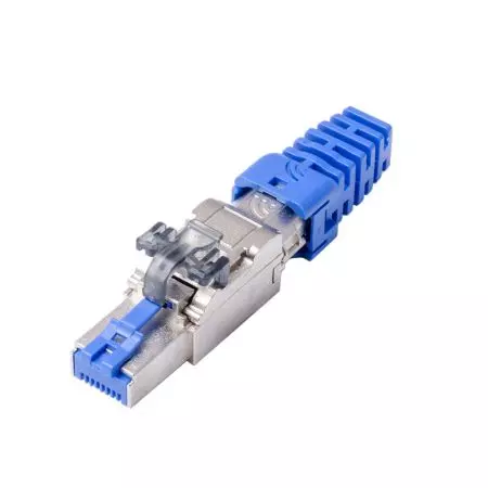
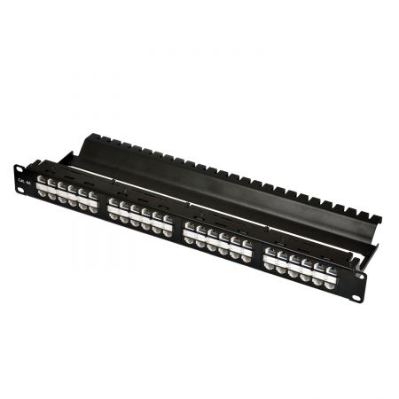
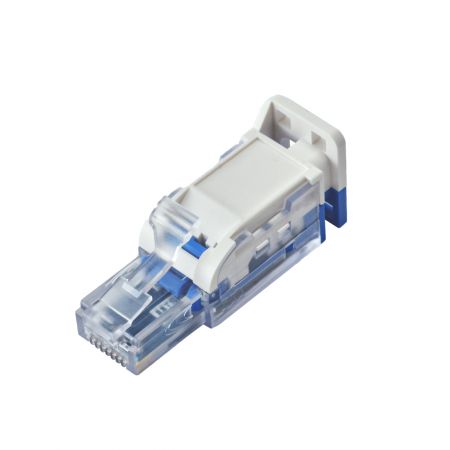
Surface-mount boxes are commonly used in smaller installations because they are compact and easy to mount near pathway exits. However, many installers prefer wall-mount patch panels (https://www.hci.com.tw/en/category/F55.html) in MUTOA deployments because they provide a more structured termination point for multiple horizontal cables.
A 12-port wall-mount patch panel aligns naturally with the standard’s twelve-work-area limit and provides a cleaner distribution point for zone cabling. Panels also simplify termination and reconfiguration because cables can be punched down in an organized layout rather than within a small enclosure. Designs that include installation brackets, such as an 89D support bracket that holds the panel during punching, can further simplify Cat 6A terminations where thicker cables require more working space.
For workstation clusters larger than twelve desks, it is generally better to deploy multiple MUTOAs and position them to serve smaller sub-clusters. This keeps patch-cord runs shorter and simplifies cable identification and troubleshooting.
3. Accessibility for Ongoing Reconfiguration
Accessibility is a defining characteristic of a MUTOA installation. Unlike consolidation points, which are typically located in ceilings or under raised floors, MUTOAs are intended to remain visible and reachable within the work area.
ANSI/TIA-568.1-E defines MUTOAs as work-area outlets that must remain accessible for moves, adds, and changes. In practice, this means technicians should be able to adjust connections directly within the workspace rather than accessing ceilings, raised floors, or other concealed locations.
In practical terms, this means the enclosure should be mounted where patch cords can be reconfigured easily during routine office changes.
Enclosure design also affects usability. Traditional surface mount boxes with front-swing lids can obstruct plug removal when multiple cords are installed. Designs with upward-retracting or "garage-style" covers keep the port area clear while patch cords are being inserted or removed, which simplifies reconfiguration in dense installations.
Another important consideration is keystone jack compatibility. Surface mount boxes should accommodate the dimensions of both standard and shielded keystone jacks to avoid fitment issues during installation or future upgrades.
Planning Before Pulling Cable
Before horizontal cabling begins, designers should verify several key points:
- Identify workstation clusters and determine their approximate center points
- Select port capacities that match the cluster size (maximum 12 work areas per MUTOA)
- Confirm mounting locations remain accessible after furniture and pathways are installed
- Choose surface mount boxes supports repeated patch-cord changes
When these factors are addressed early, MUTOA zone cabling can support workspace reconfiguration for many years without requiring new horizontal cable runs.
Many installation problems only appear later during channel certification testing. Planning patch-cord length, cord gauge, and horizontal cable distance early helps prevent unexpected insertion-loss failures during testing.
---------------------------------------------------------------If you're planning MUTOA deployments or supporting customers with open-office zone cabling designs, the enclosure design and port configuration become important parts of the installation.
Both surface mount boxes and wall-mount patch panels can support MUTOA deployments depending on the installation environment. Surface boxes are often used for small clusters or retrofit projects, while wall-mount patch panels provide a structured zone-distribution point when multiple horizontal cables terminate near a workstation group.
▶ SMB Series Surface Mount Boxes
For higher-density MUTOA zones, modular wall-mount patch panels can provide cleaner cable management, easier Cat 6A termination space, and a stable mounting surface during installation.
▶ STP/UTP Wall Mount Patch Panel
▶ Cat 6a UTP Wall-Mount Patch Panel
▶ Modular Wall-Mount Patch Panel